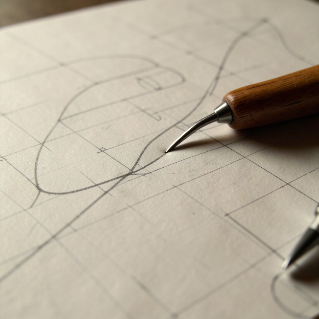
A lines plan is a conversation between three views of the same hull. The body plan shows sections looking aft or forward; the sheer plan carries buttocks and the profile; the half-breadth holds waterlines. Until you can follow a station from one view to another without losing the edge of the garboard, software will only hide the confusion.
In the Coventry studio we ask new diploma learners to trace a study craft with a soft pencil and a flexible curve. Mark the intersections where a waterline meets a station. Check that the same point appears on the half-breadth. The exercise is slow on purpose: it trains the eye to notice unfair spots before a fairing tool can invent them.
When you eventually open a modelling package, bring that marked print. Set your stations to match the paper. If a surface refuses to sit on a waterline you already verified by hand, trust the paper first and interrogate the control points second. Many early modelling errors are simply misplaced offsets copied from a rushed scan.
Keep a notebook of the coefficients you estimate from the plan—block coefficient, prismatic coefficient, and approximate displacement for a chosen waterline. Even rough numbers give you a language for later hydrostatic software output. Tutors can then discuss whether a fuller midbody or a finer entrance better suits the brief, instead of debating opaque mesh settings.